Paraboloid segment |
  
|
Paraboloid segment |
|
Parabolic objects are called 'Paraboloid segments' in SPRAY. They are defined in two steps. First a paraboloid surface is defined using four vectors, then a rectangular box is defined with four vectors as well. Only those parts of the paraboloid surface are taken that are inside the box.
The dialog to define the paraboloid is this:
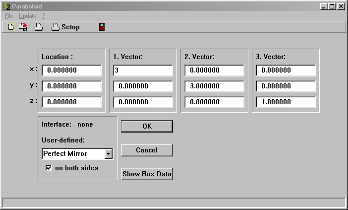
The center of the paraboloid is given by the vector called 'Location', the symmetry axis is defined by vector 3. Vectors 1 and 2 must be perpendicular to vector 3. The length of vector 1 determines the distance you have to go in the direction of vector 1 (starting at the center) in order to reach a height of 1 (measured in the direction of vector 3, with respect to the plane spanned by vector 1 and vector 2). The meaning of vector 2 is the same (only in the direction of vector 2).
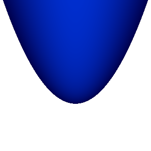
The above settings lead to the following paraboloid:
Setting the box parameters one can now cut out the wanted piece of the paraboloid. The dialog is opened by the Show box data command:
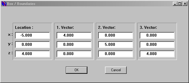
This cuts out an off-axis paraboloid segment. The new piece is this:

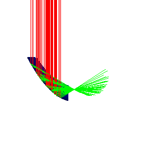
Sending a parallel beam downwards from above the mirror one gets a nice focus (which is the task of parabolic mirrors):
The definition of the interface covering paraboloids is the same as explained for rectangles.