Anisotropic layer |
  
|
Anisotropic layer |
|
Optically anisotropic layers may occur in the layer stack. They are handled using the wave propagation method described in [Parikh 1992A]. However, compared to simple layers, there are some severe limitations due to the more complex algorithm to be used in this case.
First of all, up to now SCOUT supports a special case of anisotropy only, namely uniaxial layers where the dielectric function in the direction of the layer stack normal (called the z-direction in this section) may be different from the dielectric function in the plane of the layer stacks, called the x-y-plane. You can use as many of such layers in the stack as you like.
Another limitation in combination with anisotropic layers is the following: You can have only one thick layer in the stack for which you want to switch off the narrow interference patterns (e.g. a thick, but transparent substrate). As discussed above for simple layers, this can be done setting the incoherent option for the superposition of partial waves. If you use incoherent superposition for one of the layers in the stack, and there are anisotropic layers defined, SCOUT will do the following: Lacking an elegant and fast way of averaging out the narrow interference features SCOUT does it the tedious and stupid way, namely by computing several spectra (at present: 20) with slightly varying thickness of the thick layer. The average of these spectra is then taken as the result of the computation and displayed on the screen. Obviously, the computational times will be large since many spectra have to be computed, and it may occur that the averaging is not complete and there remain some 'interference artefacts' in the spectrum. To identify these artefacts it is recommended to repeat the computation for a slightly different thickness of the thick layer and compare the results.
Uniaxial anisotropic layers require the definition of two different dielectric functions for the z-direction and the x-y-plane, respectively. For this reason, there is no entry in the 'material' column of the layer stack definition. Instead, the text 'See parameters' reminds you that you have to do the assignment differently here. Use the Edit command (or a click with the right mouse button) to open the following dialog which is used to do the dielectric function assignment:
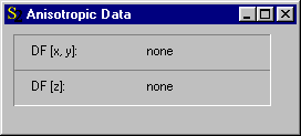
To replace the 'none' assignments you have to drag the wanted materials from the list of dielectric functions to the 'none' text and drop them there. Afterwards the dialog may look like this:
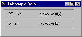
This example is taken from the second SCOUT tutorial where you can learn how to determine molecular orientation angles from infrared spectra using anisotropic layers.