Rendered view |
  
|
Rendered view |
|
Rendered views are 'photographs' of the SPRAY setup taken the following way. Rays from the observation point are drawn through each pixel of the observation window. The closest hitpoint with an object (if there is any) is taken to determine the color of the pixel:
The pixel array is drawn as bitmap in the rendered view window:

The Parameters menu command opens the following dialog which gives access to the relevant parameters:
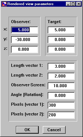
The parameters of rendered views are these:
•Observer (x,y,z): Coordinates of the observer position
•Target (x,y,z): The observer looks in direction of the target, i.e. a line drawn from the observation point through the center of the pixel array will arrive at the target position.
•Length vector 1: This is the length of vector 1 (see sketch below). Vector 1 starts in the center of the pixel array, is perpendicular to the line observer-target and lies in the x-y-plane (i.e. its z-component is zero), at least if the rotation angle is zero (see below).
•Length vector 2: Length of vector 2 which starts at the center of the pixel array and is perpendicular both to the line observer-target and vector 1.
•Observer-Screen: Distance between the observer and the center of the pixel array. Changing this distance you can easily change the viewing field.
•Angle (Rotation): The angle between vector 1 and the x-y-plane. This can be used to rotate the 'camera'. Vector 2 will follow automatically.
•Pixels (vector 1): Number of pixels in the direction of vector 1.
•Pixels (vector 2): Number of pixels in the direction of vector 2.
To avoid picture distortions the ratio of the lengths of vectors 1 and 2 should be the same as the ratio of the corresponding number of pixels.

The Draw command starts the computation of the picture. Note that the required computational time can be significant, in particular if you work with a high number of pixels. For 600 by 600 pixels SPRAY needs to determine 360000 closest hit points.
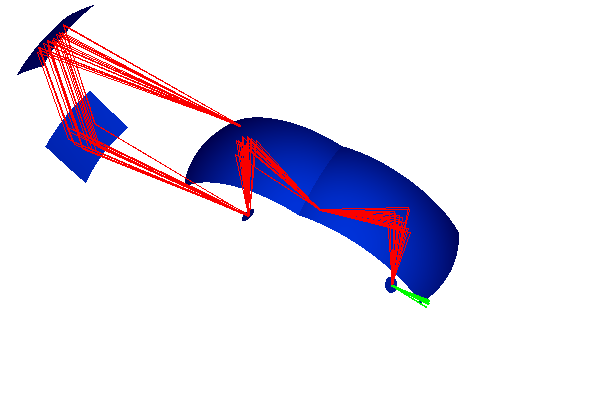
With the commands 1, 5 and 20 you can send 1, 5 or 20 test rays through the scenery. SPRAY performs the ray-tracing and the rendered view draws the path of the rays into the bitmap. The minimum of the selected spectral range (see below) is taken for the test rays. You can repeatedly use the test ray commands to create more and more rays in the picture:
It is not checked if parts of the rays are hidden by some objects - SPRAY simply draws the complete paths. Rays that do not hit any object of the scenery and escape to infinity are drawn as short lines in a different color:
If you have opened several rendered views (with different observation points and directions, for example) the test rays are drawn in each view.