Optical rays change their direction if they hit an interface between materials of different refractive index. Hence interfaces play a very important role in ray-tracing simulations. In the following we will simulate how radiation travels through a solid cylinder covered by a thin absorbing film.
However, before we define our first SPRAY interface we need to have at least two different materials (or refractive indices). Up to now our list of materials contains vacuum only. Hence we have to create a new entry. Setting up new materials is not easy since you have to know a lot about materials and their optical constants. For the present exercise, however, a very simple model will do the job. For the cylinder material we will use a constant and real dielectric function, which means that there is no dispersion and no absorption. In this case the refractive index (which is the complex square root of the dielectric function with positive imaginary part) is also real.
Open the list of materials. Select the object type 'Dielectric function model' and press the '+' button to create a new dielectric function object. Overwrite 'dummy name' by 'Fiber core' and open the new object in the treeview. Select the Range command and set a spectral range 500 ... 5000 1/cm with 100 data points. Then press the 'a' key on the keyboard for an automatic scaling of the graph. You should have arrived here:

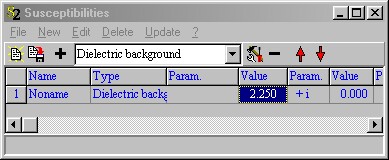
The new object has a subbranch in the treeview called Susceptibilities to open another list which contains the susceptibility contributions to the dielectric function. Select there the new type 'Dielectric background' and create an entry of this type by pressing '+'. Move the cursor to the '1.000' cell and change it to '2.25':
Close this list and select 'Recalc' in the 'Fiber core' window, followed by another 'a' for automatic re-scaling:
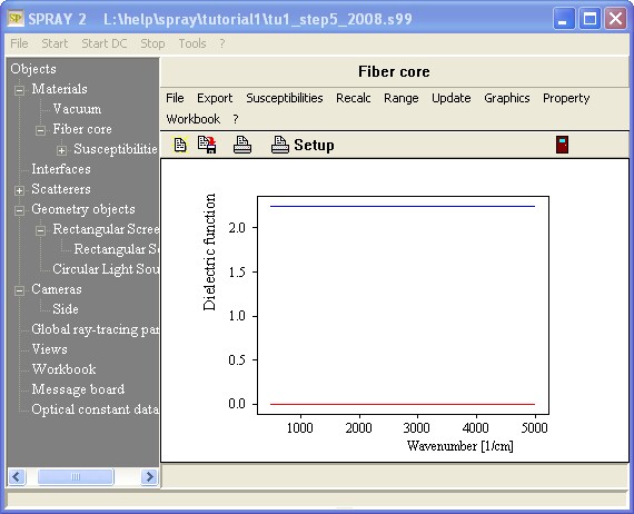
The blue line shows the real part of the dielectric function (=2.25) whereas the red line displays the imaginary part (=0). The corresponding refractive index of this fiber core material is 1.5, like that of glass in the visible spectral range. Later on we will create more complex optical constants but for the moment this one will be good enough.
We can now define the first interface that we will use for the cylinder walls in the next section. Open the list of interfaces by right-clicking 'Interfaces' in the treeview.
Select the new object type 'Layer stack' and create an item of this type ('+' button). Rename the new entry (initially called 'Dummy name') to 'Vacuum-fiber'.
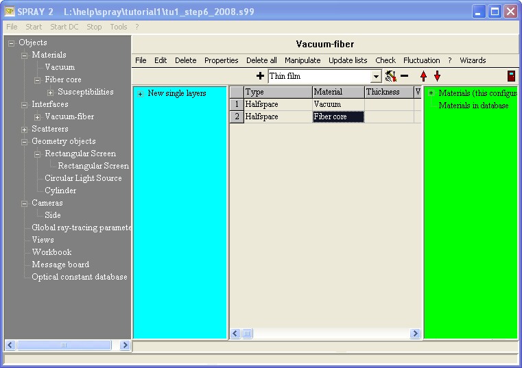
Open the new layer stack object in the treeview. You are now here:

The layer stack defines an interface between the top halfspace and the bottom halfspace. Later we will add a thin film (representing a coating of the cylinder) but at present we just want to replace the vacuum entry of the bottom halfspace. Drag&drop it from the treeview:
We are now ready to 'coat' a geometric object like a cylinder with the interface we just defined.
(The present status can be found in the configuration file tu1_step6.s99).